Repackaging A123 cells from DeWalt DC9360 batteries
WARNING -- THE BATTERIES SHOWN ARE VERY POWERFUL, AND WORKING ON THEM IN THE MANNER SHOWN HERE IS VERY DANGEROUS. I AM NOT AT ALL RECOMMENDING THAT ANYONE UNDERTAKE THIS ACTIVITY (AND WOULD PROBABLY NOT DO IT AGAIN MYSELF!). IF YOU UNDERTAKE A SIMILAR ACTIVITY, YOU ARE RESPONSIBLE FOR USING APPROPRIATE SAFETY MEASURES (I WILL NOT ATTEMPT TO ENUMERATE THEM ALL).
Note that Valence sells EV-sized batteries with built-in battery management. They are probably cheaper than buying DeWalt batteries, even on ebay...
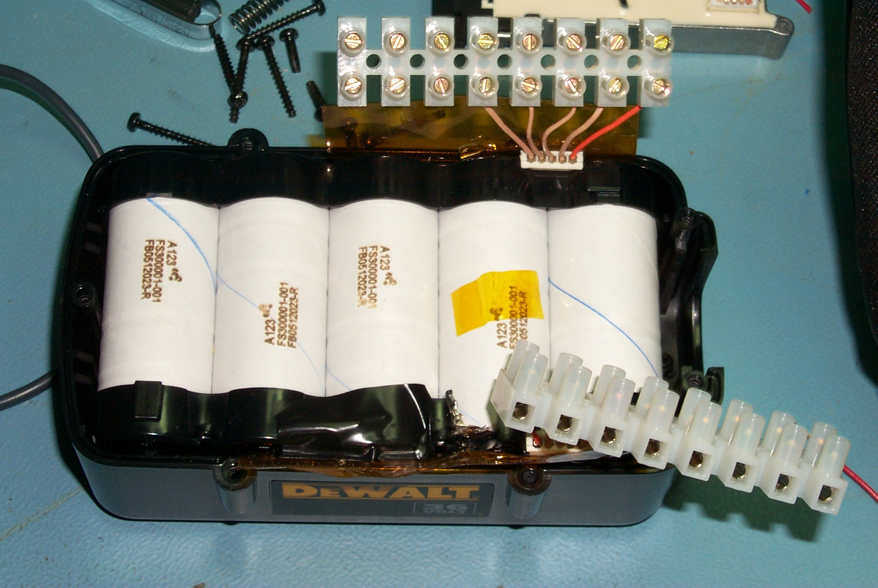
Out of 115+ batteries, I managed to short out 3 momentarily while taking them apart. The following picture is one where the case of the BMS (which is connected by 2 wires (not one) to the negative lead) touched the plus lead momentarily. The heat was enough to desolder the plus lead from the plus terminal. In another case, the small intercell connector vaporized (it acts as a fuse).
Remains of BMS and desoldered plus lead.
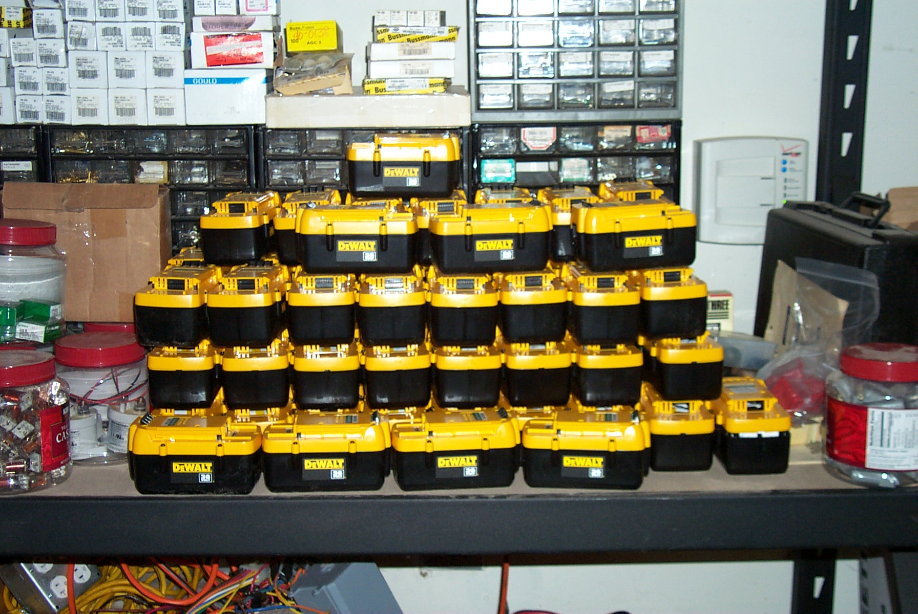
Still here? First you get a lot of DeWalt DC9360 batteries. Ebay combined shipping is good!
The DeWalt batteries use a special tamper-resistant screw, so you have to get a tamper-resist tool to unscrew them.
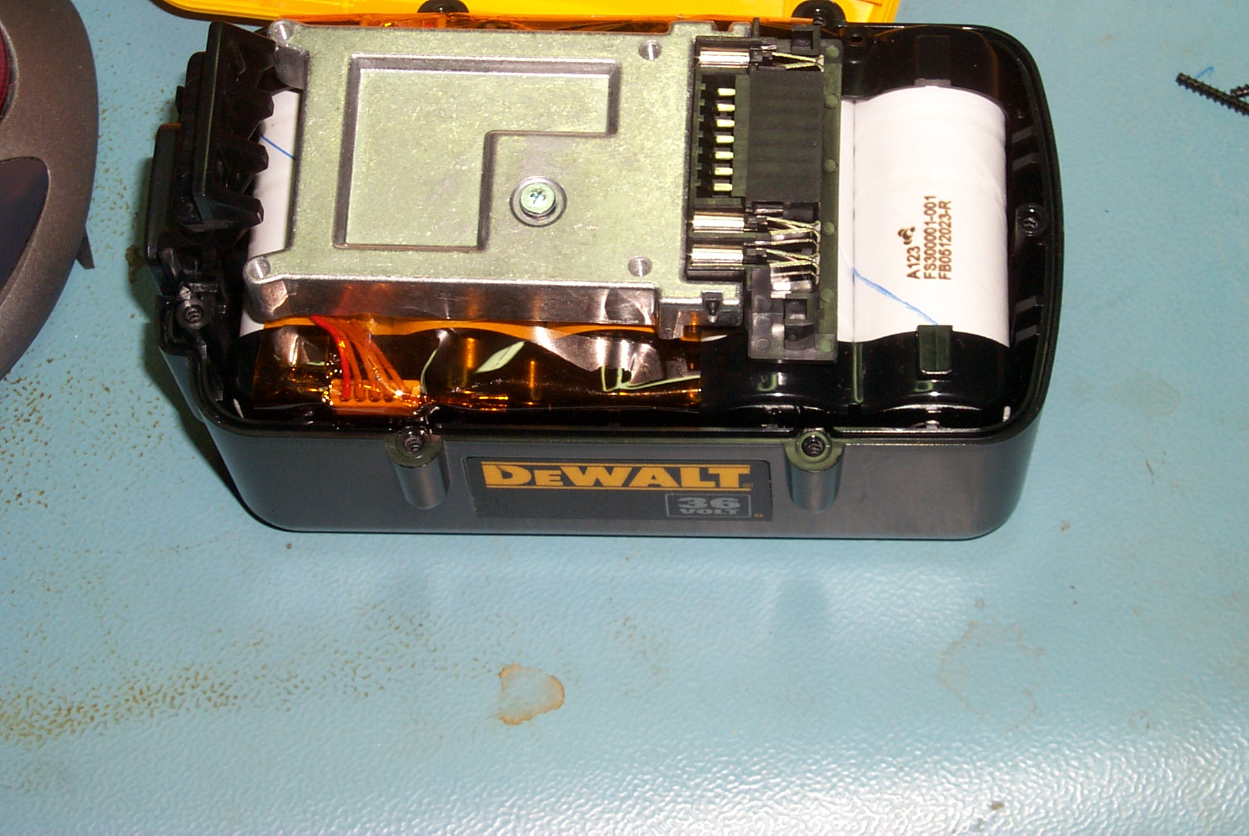
DeWalt DC9360 with top removed.
Carefully lifting the BMS unit to avoid touching the metal case against the positive terminal, and disconnecting one BMS connector, you can access the wires. Underneath the BMS module.
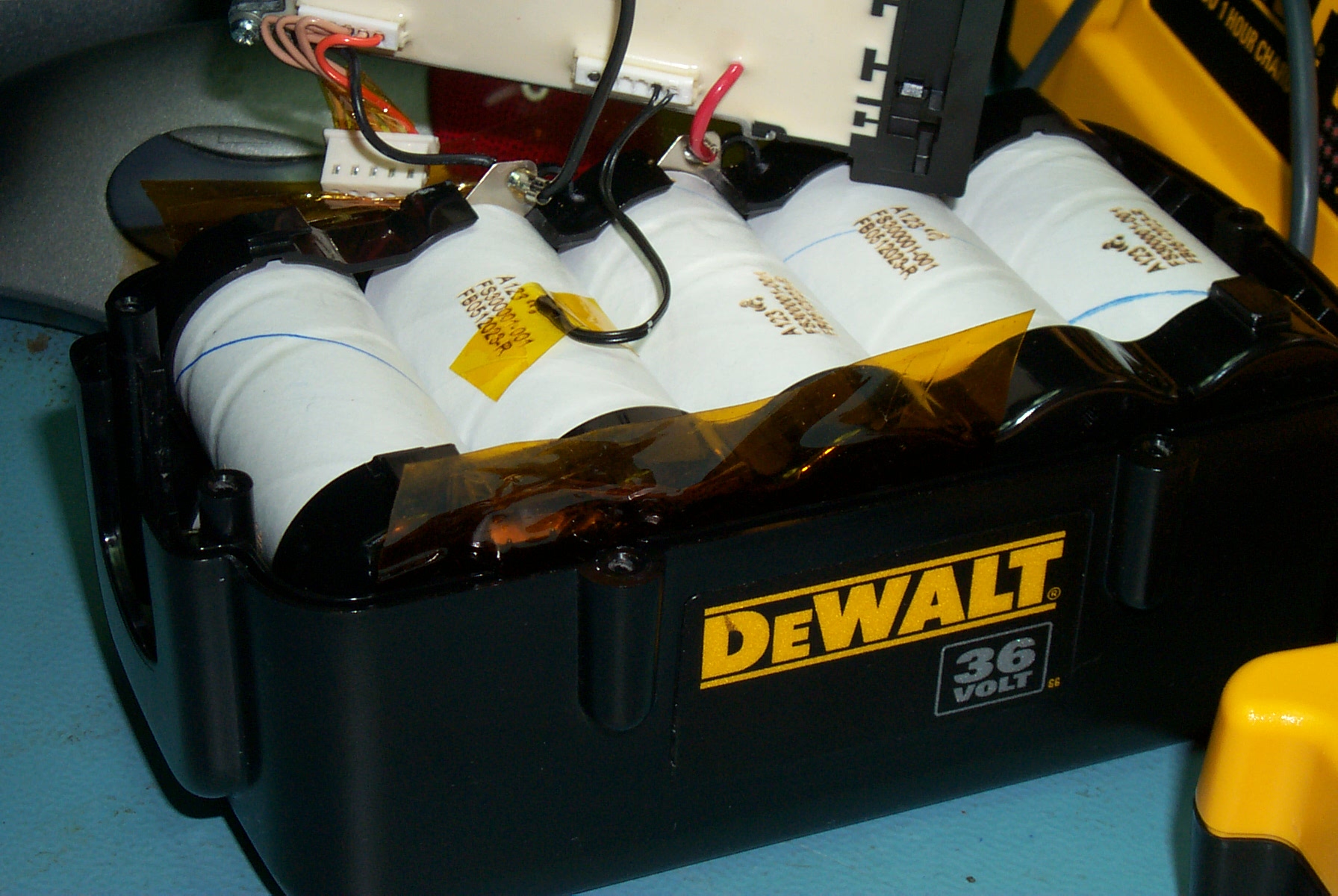
After cutting the wires next to the BMS module, I tape the plus wire with electrical tape to avoid shorts.
After removing the BMS module.
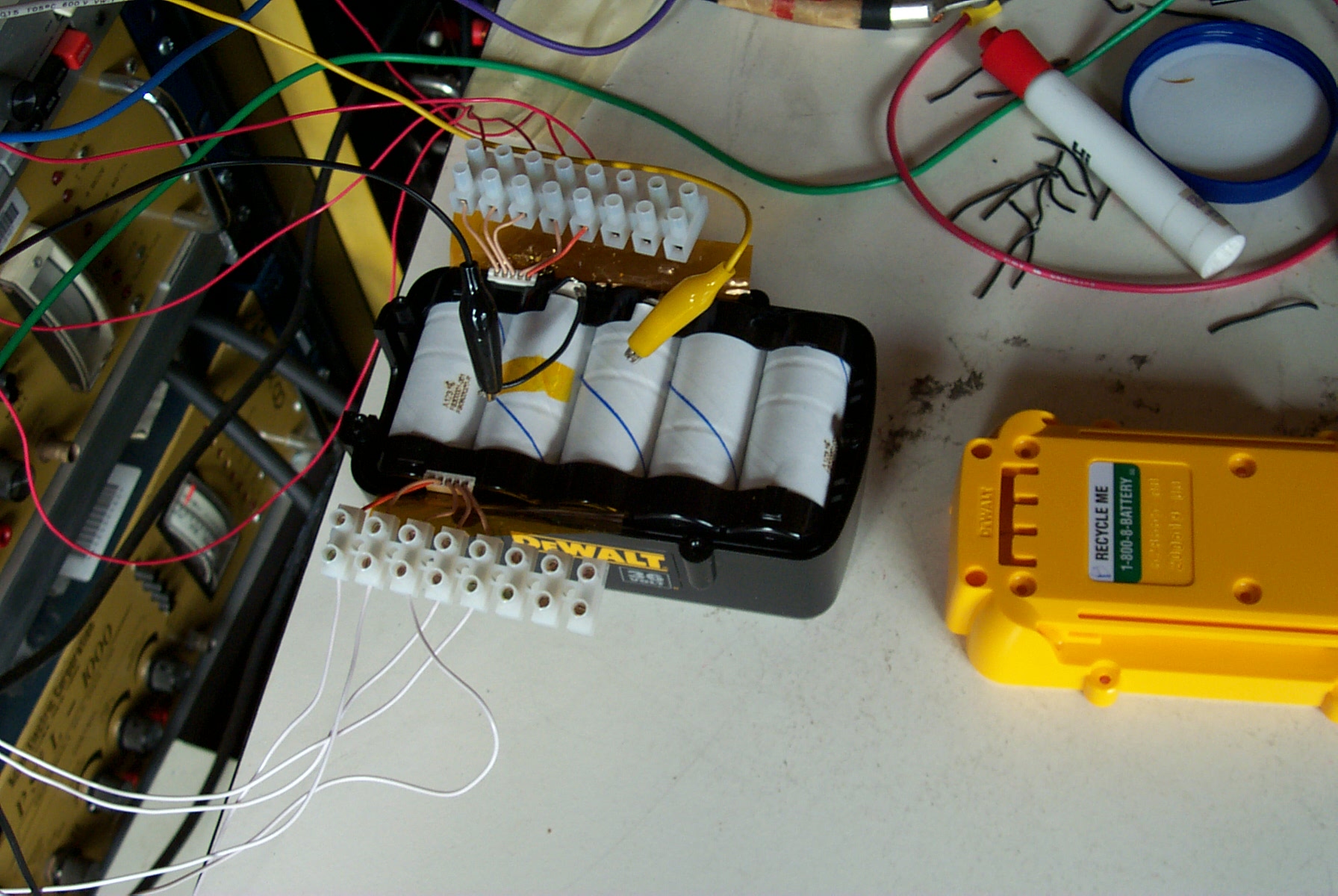
The BMS connectors are handy for charging individual cells. They connect to the intercell connections, but the plus and minus leads for the battery are needed for the end connections.
Here alligator leads are the plus (yellow) and minus (black), while the intercell connections are made via the BMS connectors. Here I am charging using 10 bench supplies at CC 2A and CV 3.6V. However, I have since moved to charging only the odd or even cells at once. This prevents strange effects when a wire becomes loose, and you end up charging two cells in series with two power supplies in series.
I noticed that even some new in factory packaging DeWalt cells will not charge with the DeWalt charger. This is because some cells have a higher self-discharge rate, and if they sit for too long some cells drop below 2.9V. When this happens, the DeWalt charge signals a bad battery. However, after charging individual cells, they work just fine!
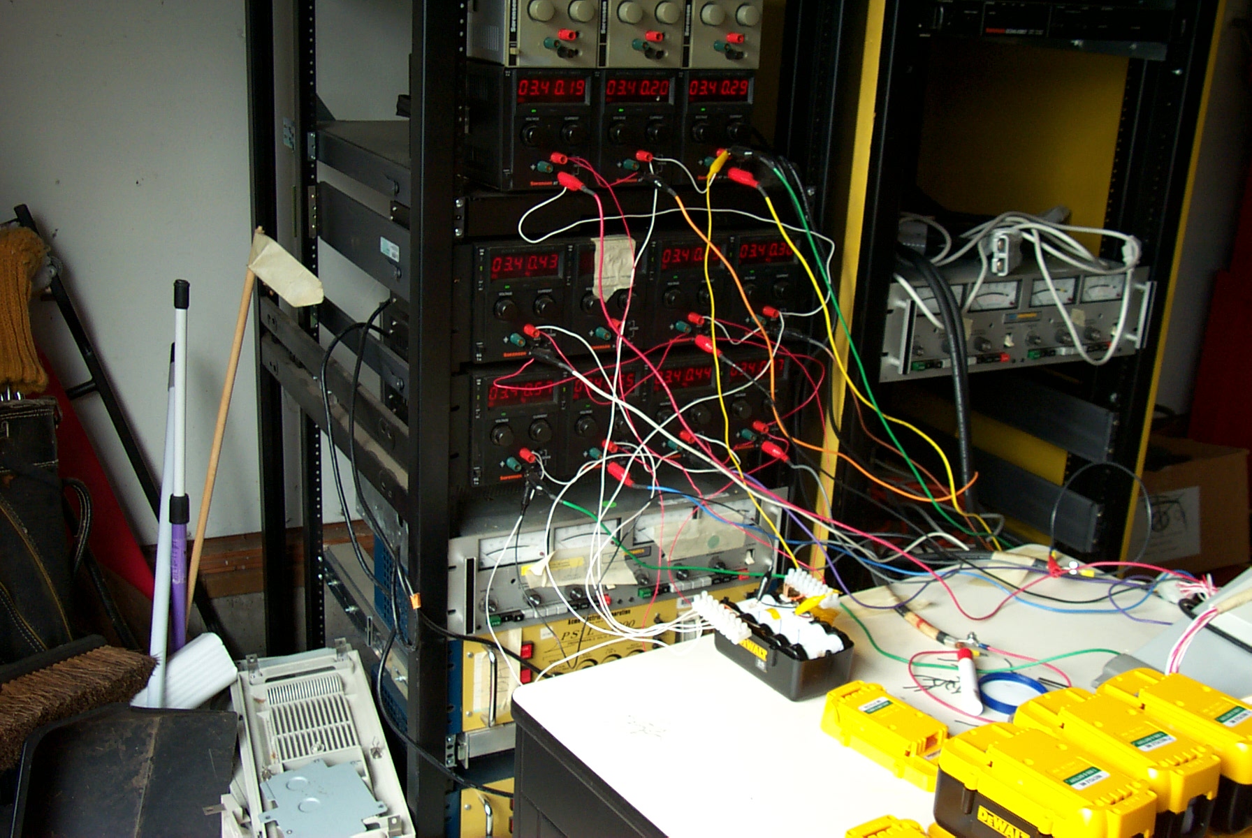
Here is a view of the 10 Sorenson bench supplies during individual cell charging.
Ten bench supplies charging individual cells.
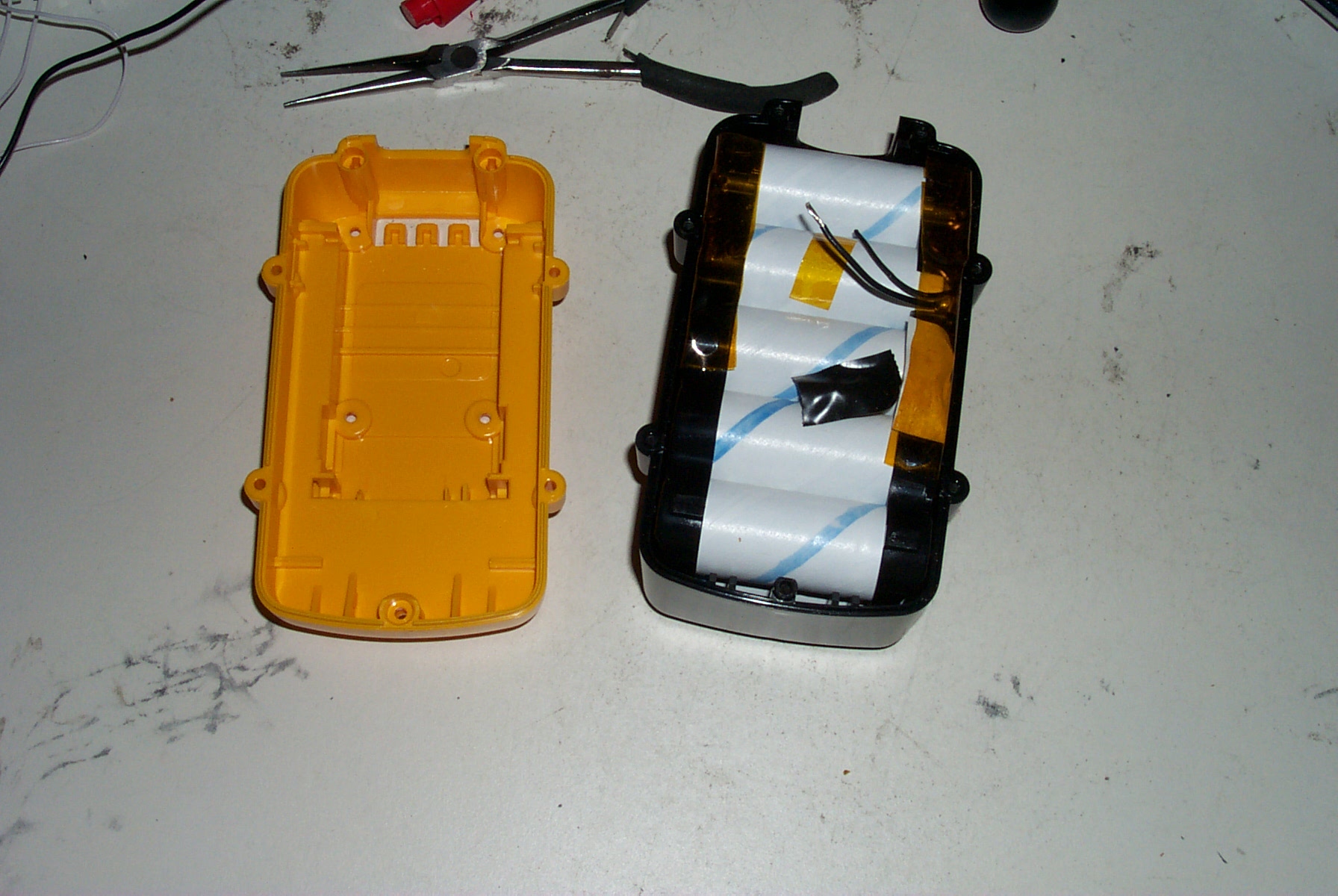
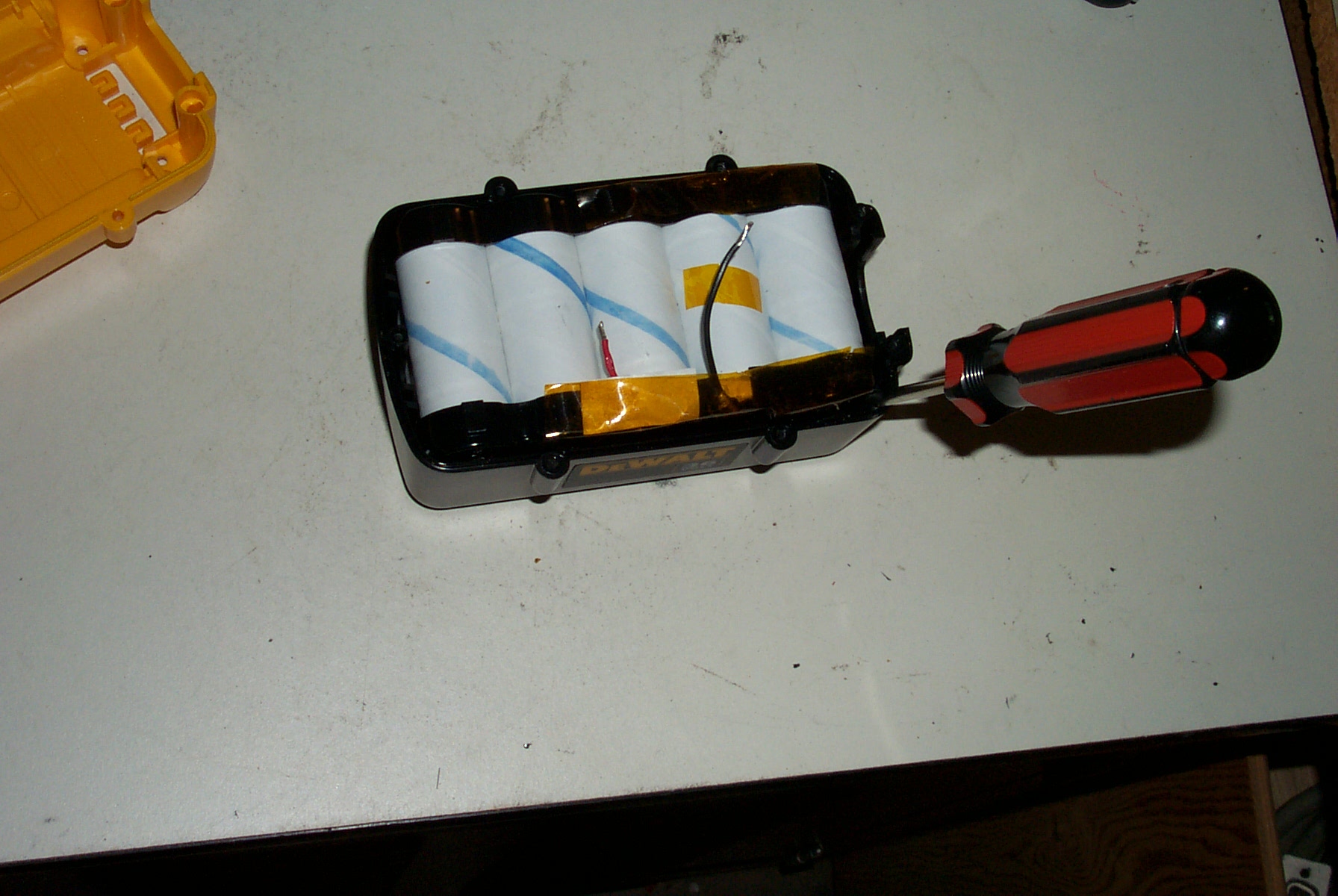
After the cells are charged, it's time to remove them from the DeWalt package. There are four pry points on the corners. Alternate to gradually work the cell carrier out of the bottom enclosure.
Removing cells from the battery.
After removing them, the 10 cells are still welded to interconnects. It is easy to short the plus and minus terminals, as they are right next to each other!
Very carefully (trying not to break any welds to the cells), the cells can be unfolded into more or less a straight line.
The cells are straightend so that they form a straight line. The interconnects are folded back on themselves. I mark the positive end with a red marker. You really don't want to get the polarity mixed up when combining these strings!
I place the straightened cells in a wooden container for safekeeping, and to help keep them straight. This container holds 8 10-cell strings.
Repeating 8 times, we have a plane of 8 10-cell strings in the container. Marking the polarity clearly is important! When you are tired, you still don't want to get it wrong!
A plane of 8 strings in storage.
The plane is rolled out onto a workbench to connect the strings together mechanically and electrically. Rubber doormats are used to prevent short circuits.
Preparing to connect a plane of 8 strings.
In fact, two rubber mats are used. One on each side. Wires still can sneak underneath and short out a cell group! This happended once, but I instinctively pulled it out when I heard the snap! The wire was very hot!
Dual floor mats used to minimize accidental shorts.
Now I oriented the intercell strips to the same position, and time them together with bare 18 gauge stranded wire. This is probably too thick. (If a cell shorts, you might want these wires to vaporize like a fuse). I soldered the knots so that they would not come undone. If I used thinner wire, I could solder directly to the metal tabs connecting the cells. Be careful not to breathe the rosin core solder during soldering! I now use a powerful fan to blow rosin vapor away during soldering. I went through a pound of solder--more than I have used in my entire life.
Tying strings together between cells.
This process is repeated to construct two 8-string planes, and a 7-string plane that goes in-between. These are laid out on another work table in preparation for tying the planes together with the same 18 gauge wire. I used 4 ties between each set of cells.
Preparing to tie planes together.
Another view of the same picture... The excess from tying the plane is taped to prevent shorts, and later used to tie planes together.
Of course, the rubber mats are deployed during this process as well.
I use 2/0 welding cable for the plus and minus leads of my 230-cell batteries. I crimp a lug onto the ends, and strip the standed (19 strands) wire to allow connection to individual strings on both ends. I also have a 15-pin 600V Molex connector connected to 75K ohm resistors for measuring voltage. Eleven pins are used for voltage, and the rest can be used for temperature (not done yet). I also have a 12-pin 600V molex connector going to 11 500VDC 30A Littlefuse KLKD fuses for equalization. I did not want to build the BMS right into the battery itself (I'm really glad not to have to open them once they are built, but just plug in a new BMS or cell balancer.)
Terminals and fuse/resistor BMS cables. .
The welding cable strands are soldered to prevent unraveling.
Welding cables soldered at ends.
A close-up of the fuse cable. I'm not really happy with this--there probably is a better way to do this.
Here is a close-up of the 75K resistor cable used for cell group voltage measurement. I should have used much smaller wire. The two cables are much easier to bend than one large cable.
Voltage measurement resistor cable.
I connect 2 strands from the 2-0 welding cable to each 18-gauge wire from the DeWalt pack. One end is tied together with 18 gauge stranded wire. Masking tape helps hold the cells together until the end cable is completed.
Attaching the cables to each end.
The battery is ready for the BMS cables.
The batteries are then put into 36X3X9 inch boxes, which holes on each end for Molex BMS cables, the power leads, and ventilation. The ventilation plan is to blow air in one end and out the other. Air from a battery compartment should not be mixed with passenger cabin air. In an accident, it may be producing toxic gases (see the A123systems MSDS).
So that's it. I'm currently (Oct 13, 2007) running 5 boxes of 33V for a total pack of 166V weighing 166 lbs or so. I plan to add a 6th box to bring it up to 200V, and have room for 4 more boxes in the gas tank cavity. But for now, I'll see how well they behave before adding more in a place where it is difficult to access.
Altogether this comes to 23 X 5 = 115 DeWalt batteries. Perhaps I'll find a use for the empty boxes.
At 166V, I can drive on the freeway, but it is a bit slow going up steep hills. My Siemens AC drive takes up to 400V, and really wants about 240V to be happy. That also matches the HP of the original Insight.